When I was researching what USB power socket to buy and how to install it I found that there wasn’t a whole lot of info, so while installing my 12v USB power socket I thought i’d take some pictures to make a step-by-step walk through of installation.
N.B.: Always remember to disconnect the battery when working on car electrics.
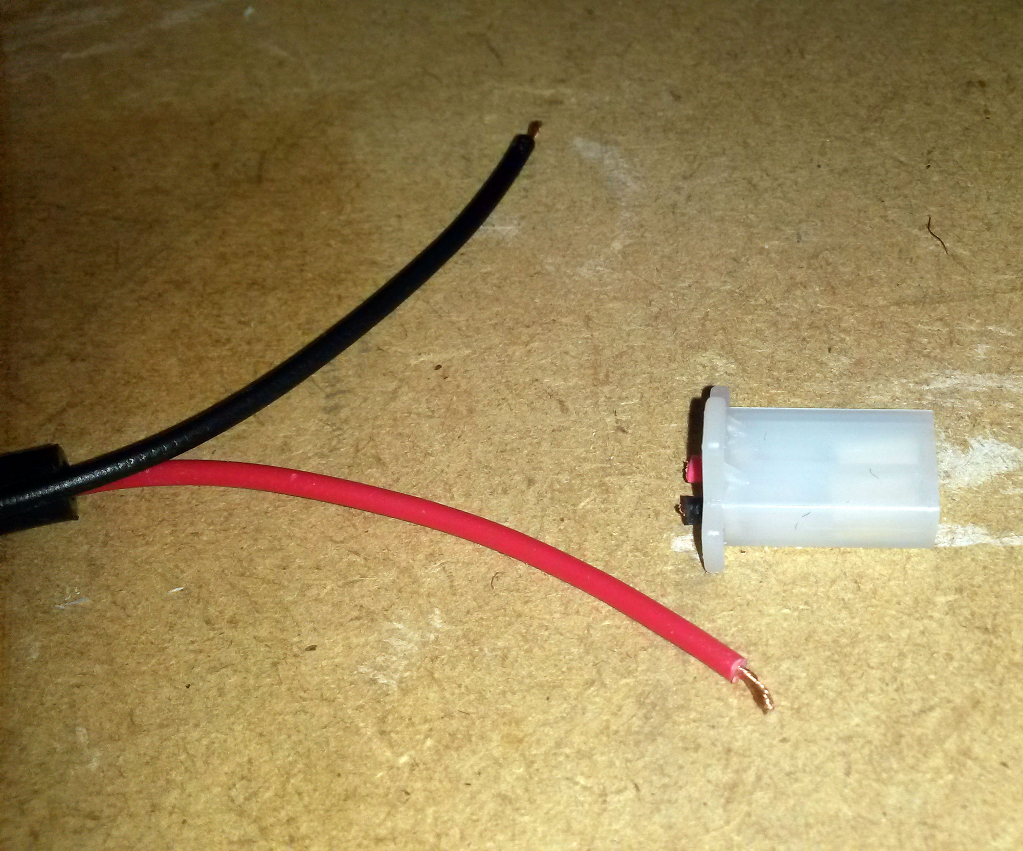
1 – I bought the 12v USB socket from eBay:
http://www.ebay.co.uk/itm/361207013974. The connector was obviously for a different vehicle, as the part was a marine socket, so I had to snip the connector off and strip the wires to fix new connectors to it.
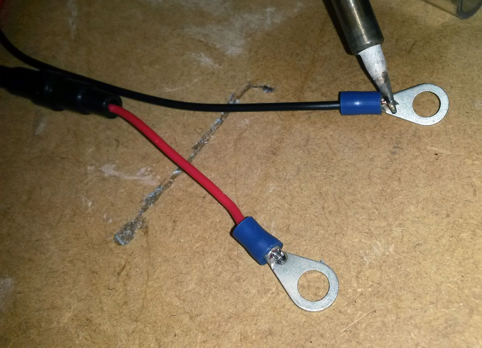
2 – I used 6mm ring connectors because the voltage points use M5 screws. A dab of solder insured they would stay fixed amid vibrations and ensure the current could flow through the ring connectors as best possible.
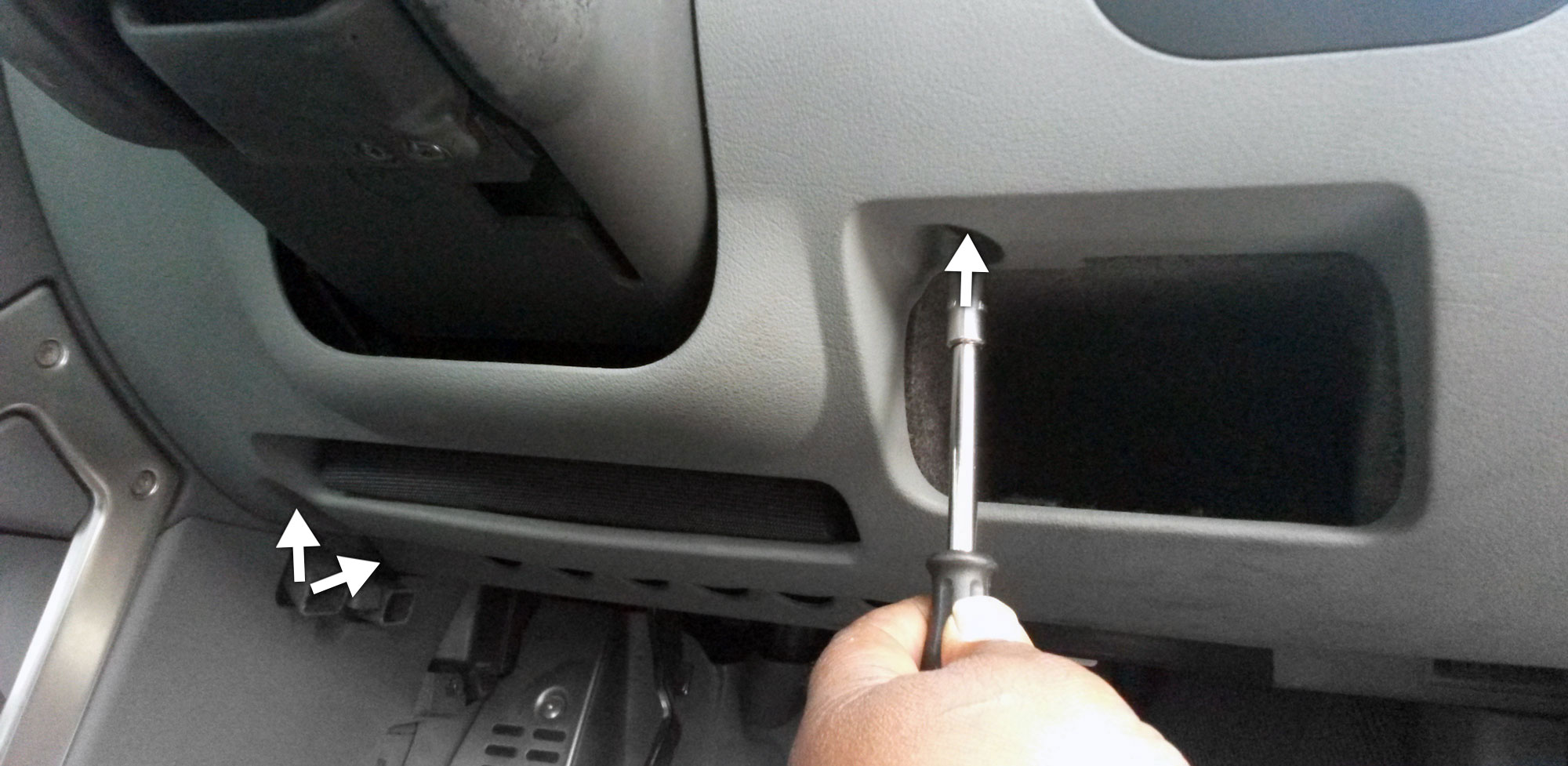
3 – Once the wires were adapted, the lower cover needed to be removed. The fixing points for the lower cover sit behind the fuse box panel. 20mm torx screws hold the lower cover to the car, these needed to be undone at the points marked with arrows.
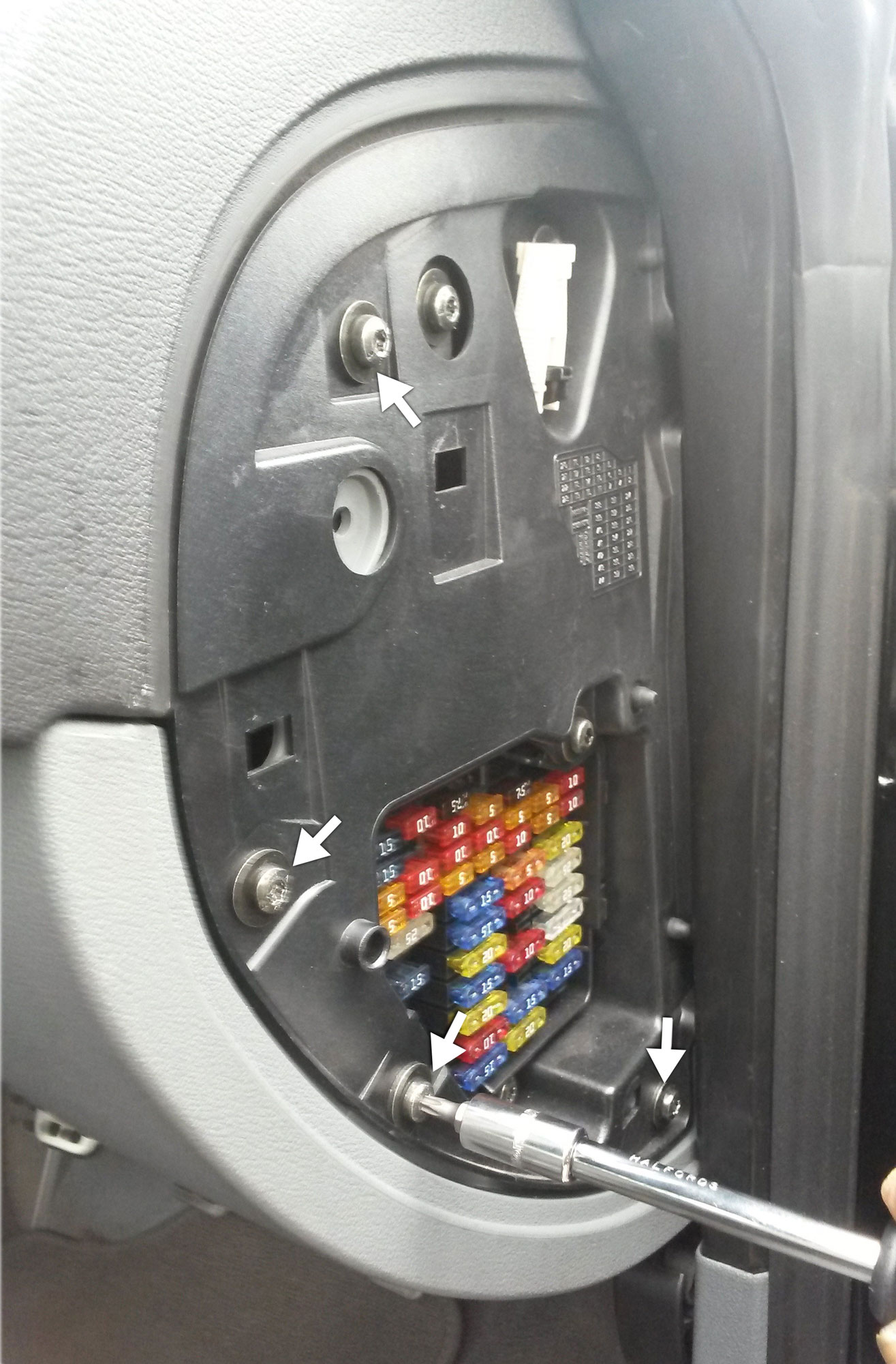
4 – There are 20mm torx screws on the actual panel itself that also need to be undone in the places indicated.
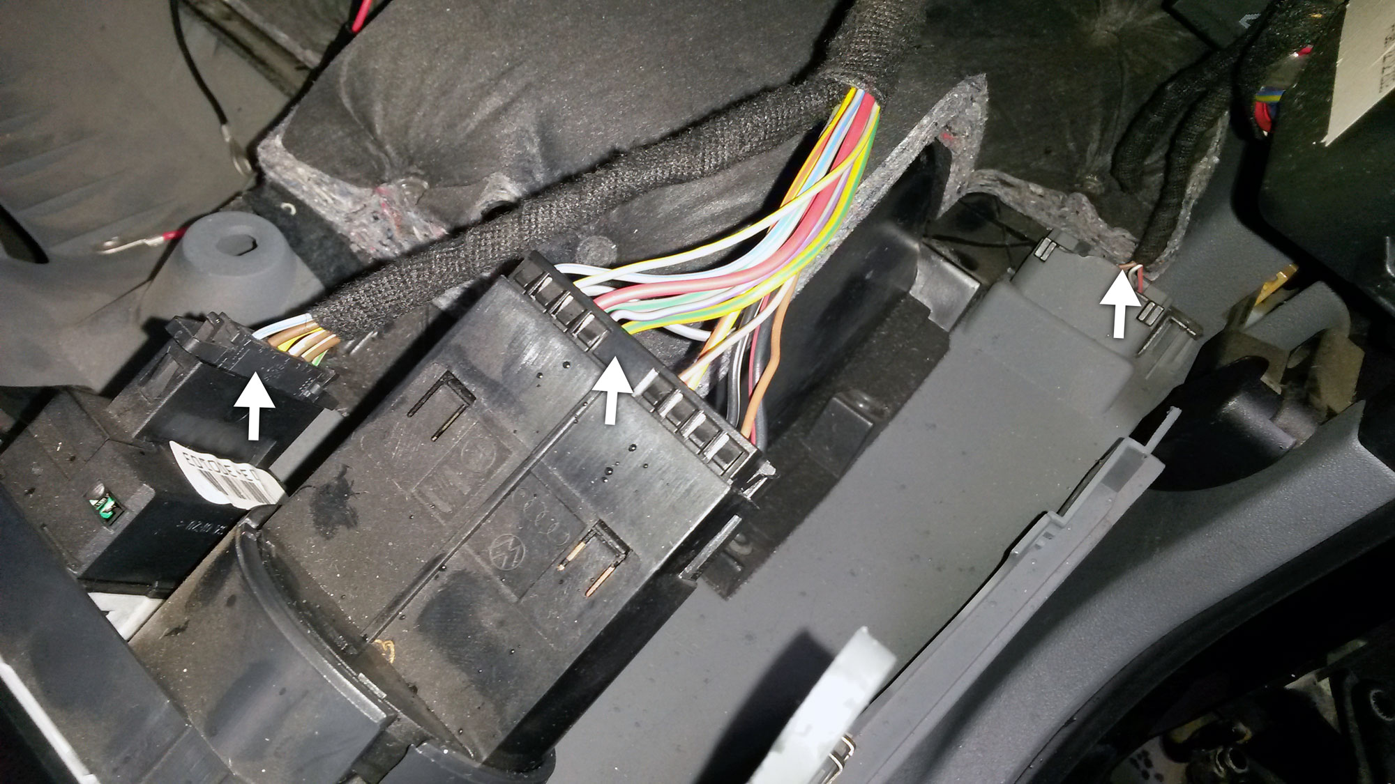
5 – The panel needed to be pulled down. In places it was a bit of a struggle, but with a bit of care it eventually pulled away from the vehicle. The connectors indicated need to be disconnected before removing the panel from the car to work on a stable surface.
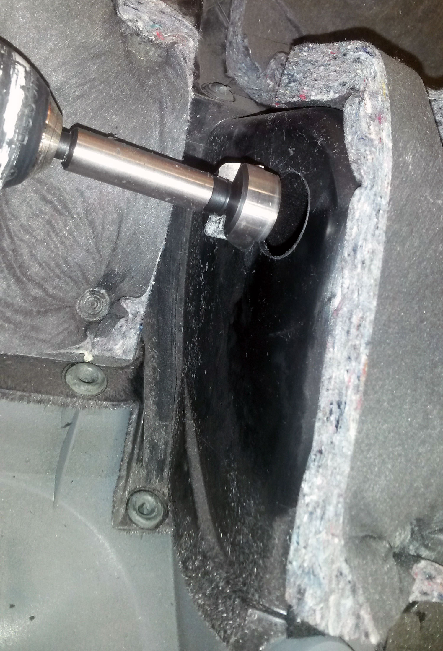
6 – I used 29mm bore drill to punch a hole through the cover. After looking at which position to place the socket I actually decided that as far back as possible and as high up as possible (while leaving about 1.5cm gap from the edges for finger space inside the hole) was the best solution for me to ensure the socket didn’t clash with the steering column when it is adjusted for comfort.
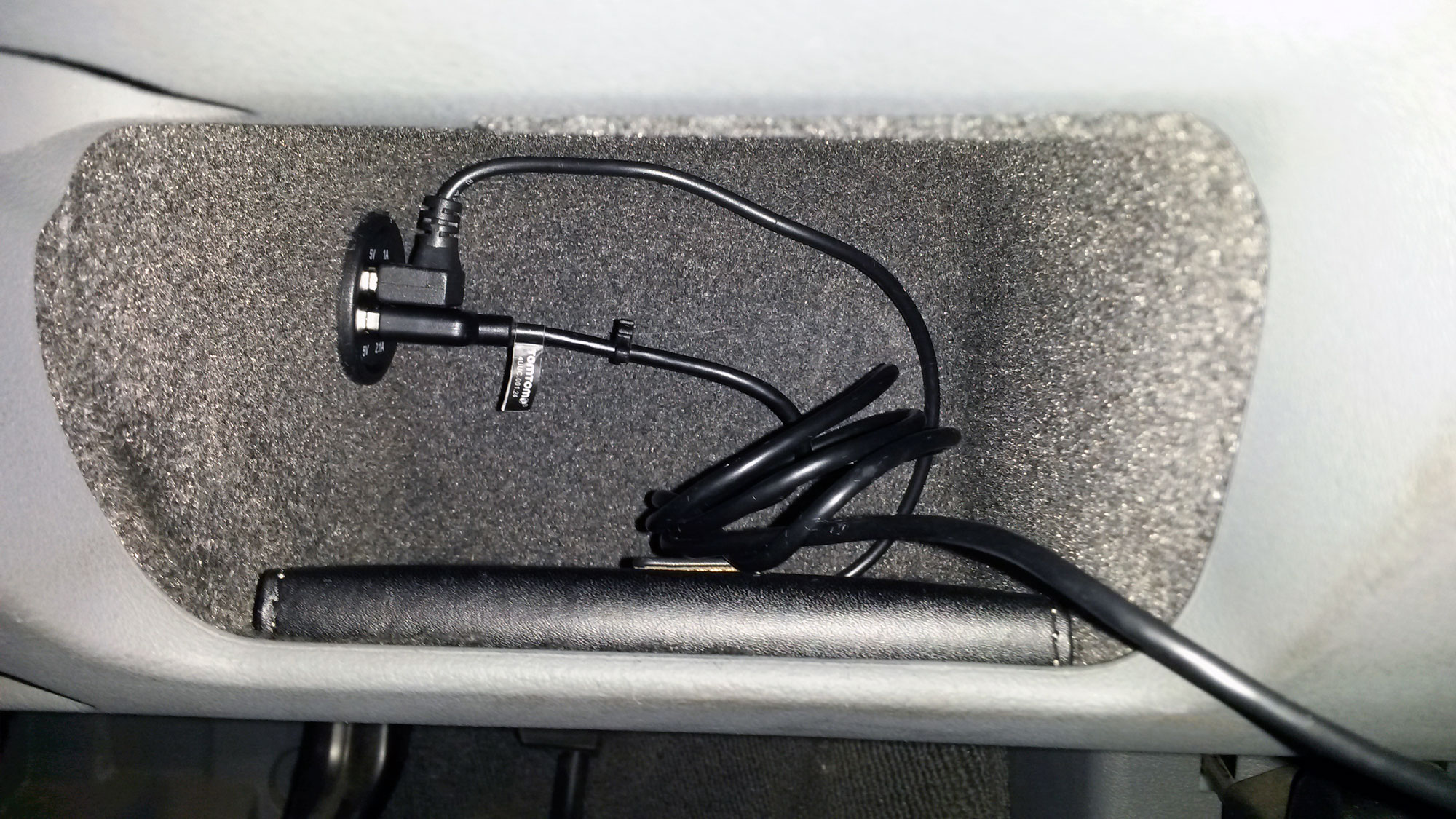
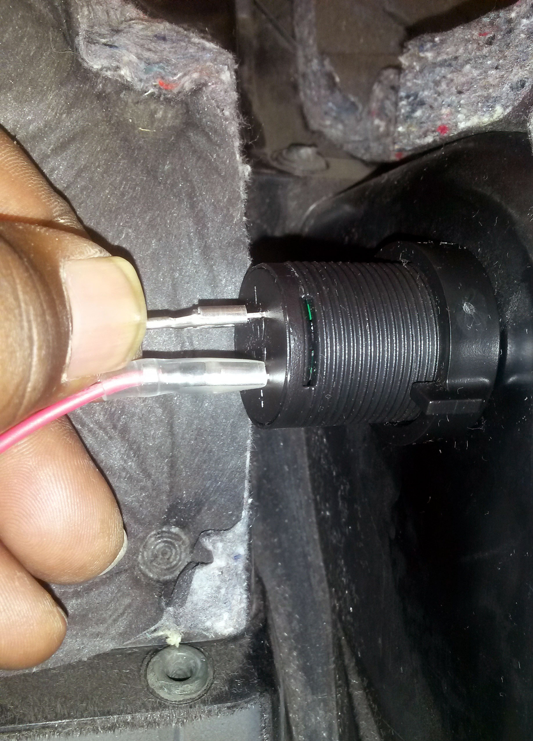
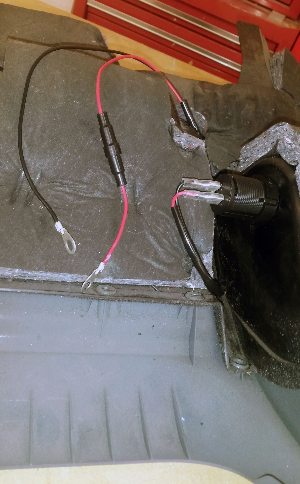
7 – Once the socket was popped through the hole the plastic nut needed to be tighten firmly to ensure there was no rotation of the socket in the hole. I actually chopped off the lid on the rubber cover that came with it socket, but I kept the rubber ring on the socket to ensure the socket gripped around the hole well.

8 – Flat connectors attached.
9 – The final assembly looked something like this.
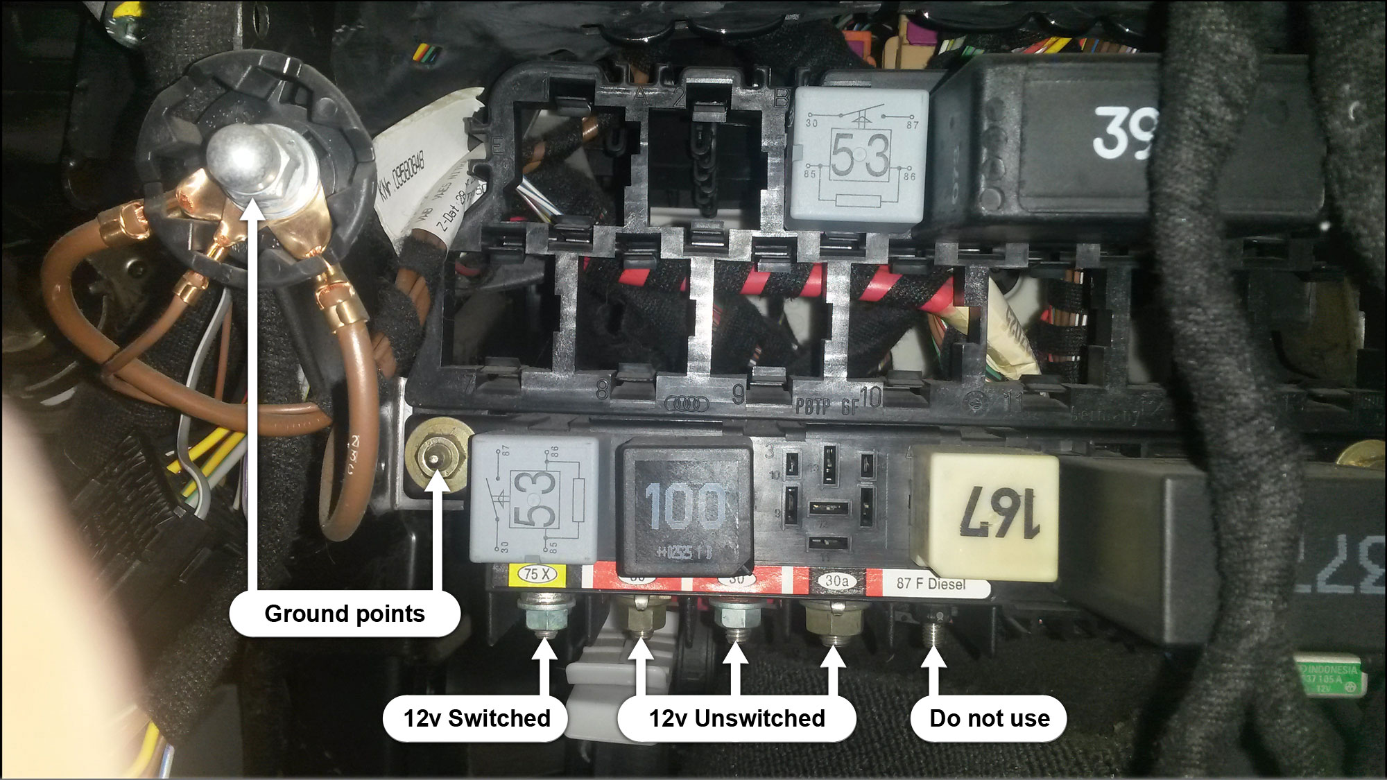
10 – Back at the car, with the new socket installed onto the panel, the next thing to concentrate on was the Busbox. This photo shows the connection points to be aware of; the ground for the black wire and the 12v live connectors for the red wire. The switched point will turn the power to the socket on and off with the ignition, and the unswitched 12v point will constantly power the socket regardless of the ignition. I chose the 12v unswitched point to power my socket because sometimes I need to charge my phone while I’m away from the car but I suppose this choice is personal preference really.
11 – The nuts on the connectors needed a 10mm socket to disconnect the nuts from the screws.
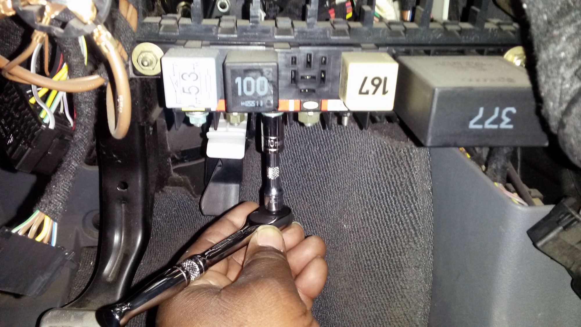
12 – Couldn’t have been easier to pop the ring connectors on then put the nuts back on with the 10mm socket. The actual points i picked we actually the easiest to undo — anything to make life faster & easier as I only had about an hour to do this in my lunch break.

13 – The cover was carfully refitted; doing steps 5, 4, and 3 in reverse.
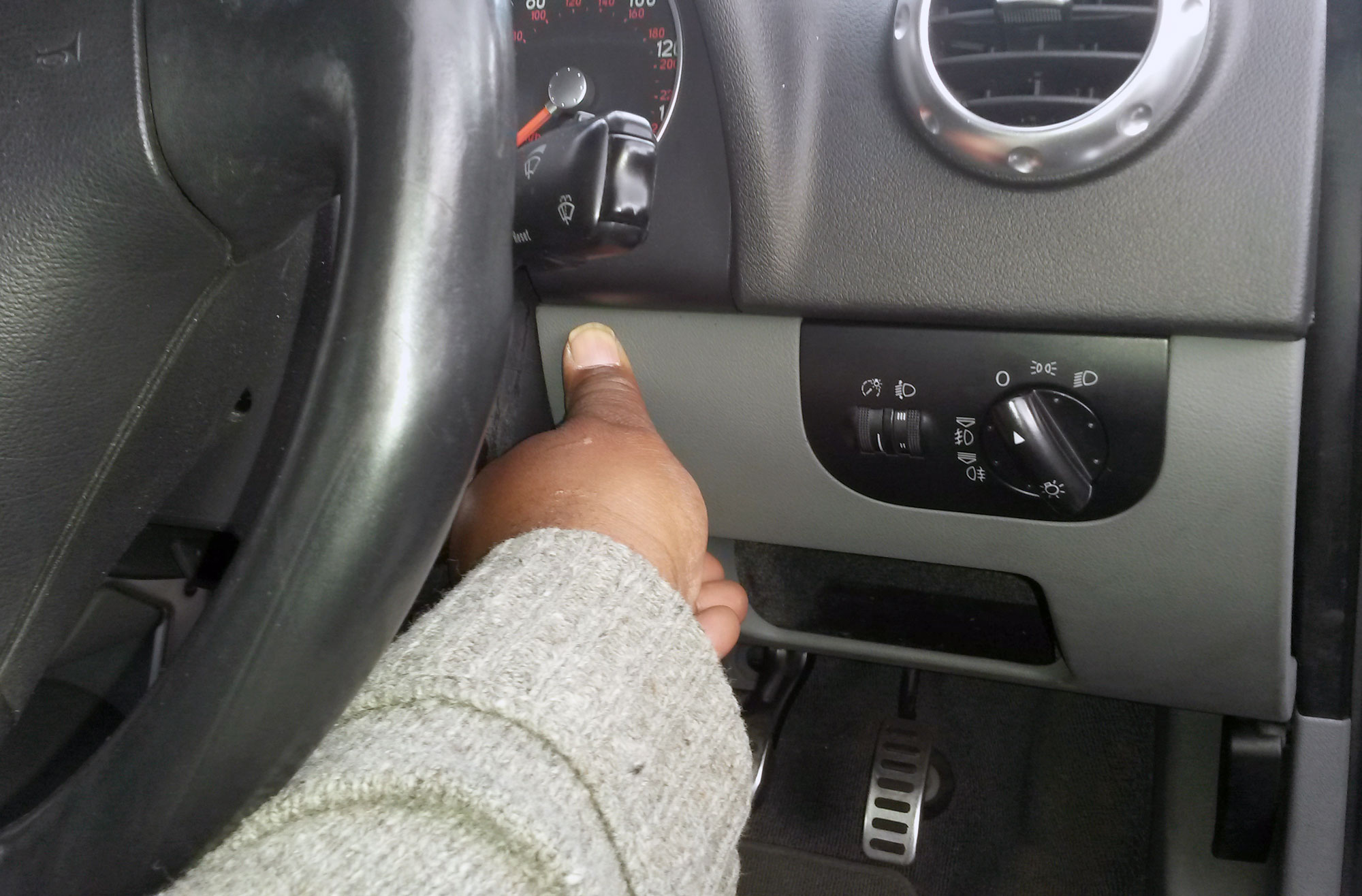
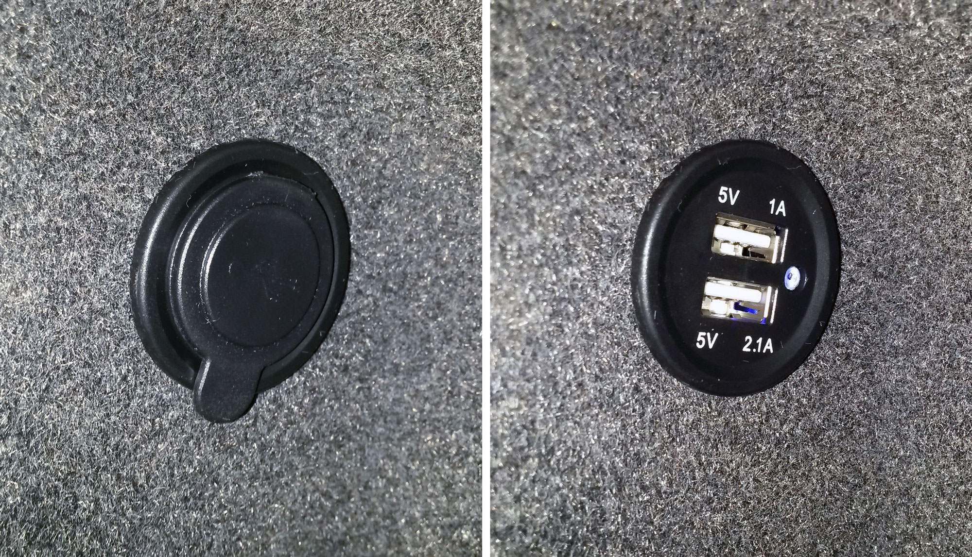
14 – Then, TADA! The socket was ready to be used.